
Advanced Navigation’s precision navigation technologies for unmanned systems leverage fiber optic gyroscope (FOG) innovations.
While the exact inception of the gyroscope is unclear, its evolution has made it a vital instrument in navigation.
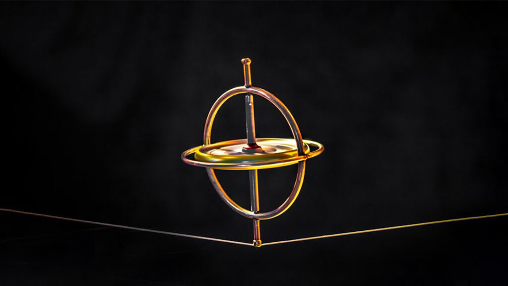
The concept may have been inspired incidentally a spinning top maintains its equilibrium, even on sloped surfaces.
Fundamentals of Gyroscopic Sensor Technology
By utilizing a flat disc with a pin at its center, researchers could closely examine the balancing effect of a spinning top. Increasing the mass of the disc, particularly at its edges, and enhancing its spin speed improved its stability. A higher spin rate or moment of inertia results in increased angular momentum.
To delve deeper into this phenomenon, scientists placed the spinning disc within a mechanical framework, allowing for manipulation without direct contact.
friction was minimized through bearings or similar devices, enabling the disc to rotate freely within the frame. Adjusting the frame’s angle while the disc spun revealed a resistance to repositioning, a phenomenon later termed gyroscopic precession.
Exploring Gyroscopic Precession
Gyroscopic precession refers to the behavior of a spinning object when its axis of rotation is tilted.The object resists this tilt, generating a torque that is perpendicular to both the external force and its axis of rotation, adhering to the right-hand rule.
For instance, consider an unbalanced spinning top. Rather of toppling over or correcting itself—actions that would contradict the conservation of angular momentum—the top traces a circular path. The torque from gyroscopic precession acts at a 90° angle to the gravitational force, resulting in this circular motion.
Rather then directly opposing an applied torque, the resistive force of the spinning object manifests perpendicularly to the applied force.
integrating the Gyroscope with a Gimbal
By attaching the spinning disc to a gimbal, researchers could better control and study its properties.A gimbal is a framework that allows different components to move independently. in this configuration, the inner gimbal, which holds the disc axle, connects to an outer gimbal at a right angle. Pivot points reduce friction, preserving the gyroscopic effects.
The outer gimbal is fixed to a stable frame, creating a traditional mechanical gyroscope capable of rotation along the X, Y, and Z axes.
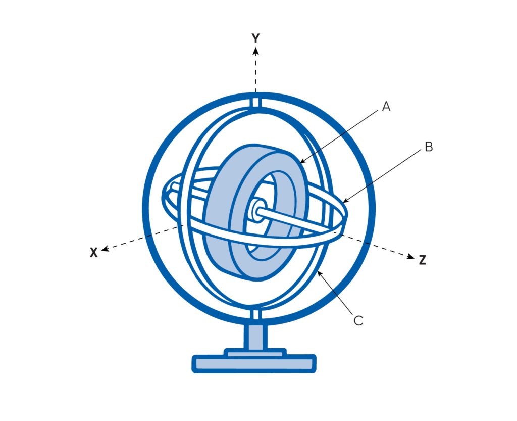
A traditional mechanical gyroscope design. The spinning disc (A) is mounted to the inner gimbal (B),which is positioned at a right angle to the outer gimbal (C). The outer gimbal can rotate relative to the mounting frame, allowing the spinning disc to maintain its original axis of rotation regardless of the gyroscope’s orientation.
Gyroscopic Motion and Conservation of Angular Momentum
Gyroscopic motion illustrates a spinning object’s inclination to maintain its rotational alignment, a phenomenon driven by angular momentum that resists alterations to the axis of rotation.
The gimbal configuration shows that a spinning disc’s rotational axis remains stable even when the gyroscope tilts or rotates in three-dimensional space. this stability is a result of angular momentum conservation. Any changes in the gyroscope’s orientation adjust the gimbal positions, ensuring the disc retains its original axis of rotation. Discs that spin faster exhibit greater angular momentum, enhancing their resistance to reorientation.
The gyrocompass: An Essential Navigation Instrument
The advent of electric motors allowed for continuous, high-speed spinning of gyroscopes, making them suitable for prolonged use. Navigators soon recognized the potential of aligning gyroscopes with Earth’s rotational axis to accurately determine true North, overcoming the limitations of magnetic compasses.
In the early 1900s, Hermann Anschütz-Kaempfe introduced the gyrocompass, a practical navigation device for steel-hulled ships. Unlike magnetic compasses, which can be influenced by ferrous materials, gyrocompasses provide precise headings relative to true north. Heading determination methods include graduated rings indicating gimbal rotation or torque measurements reflecting directional shifts.
Inertial Navigation Systems (INS)
The emergence of autonomous systems has created a demand for highly reliable navigation and control technologies. Inertial navigation systems (INS) have become essential, providing roll, pitch, and heading data for various vehicles.
INS devices utilize sensors to detect linear movements and gyroscopes to monitor rotational changes. Magnetometers or fiber-optic gyroscopes can provide heading data, while GNSS often delivers absolute positioning data. In the absence of GNSS signals,INS employs dead reckoning to estimate positional changes based on motion data.
Contemporary Gyroscope Sensor Technology
Recent advancements in electronics, computing, photonics, and manufacturing have revolutionized gyroscope technology over the last century. While the core concept remains intact,innovations have enhanced accuracy,reduced size and weight,and lowered costs. These improvements support applications across commercial, industrial, and defense sectors.
The modern need for precise data collection has further propelled gyroscope development. Navigation systems for space exploration, underwater research, robotics, and unmanned vehicles depend on highly accurate gyroscopes. These systems contribute to cost reduction, increased efficiency, and minimized environmental impact.
MEMS Gyroscopes
Micro-electromechanical systems (MEMS) gyroscopes, which emerged from integrated circuit technology in the 1960s, combine electrical and mechanical components into a compact chip format. MEMS devices are cost-effective and widely utilized in inertial navigation systems, ranging from consumer products to tactical applications.
MEMS gyroscopes typically leverage the Coriolis effect to detect rotational motion. In these systems, a proof mass oscillates within a frame, and rotation induces vibrations perpendicular to the motion. these vibrations result in capacitance changes that are proportional to the detected rotation.
While MEMS gyroscopes measure rotation within the device’s inertial reference frame, they do not provide heading information. Additional sensors, such as magnetometers, are necessary for this purpose.
Video Player
00:00
00:00
00:13
Use Up/Down Arrow keys to increase or decrease volume.
This illustration demonstrates the operation of a basic MEMS Coriolis effect gyroscope. The springs (A) secure the proof mass (B) within the inner frame (C),establishing the drive axis. The inner frame is isolated from the outer frame (D) using springs (E) positioned at 90° to the drive axis, forming the sense axis.
The inner frame features several protruding fingers (i). The fixed electrodes (ii) create differential capacitors, with a finger from the inner frame situated between the capacitor electrodes. During rotation, the Coriolis effect causes the proof mass/inner frame to move against the direction of rotation, resulting in capacitance changes proportional to the rotation rate.
Fiber-Optic Gyroscopes
Introduced in the 1970s, fiber-optic gyroscopes provide extraordinary accuracy and resistance to drift, making them suitable for advanced navigation and strategic applications. A FOG consists of optical fiber coils,a laser source,and an optical receiver.
FOGs function based on the Sagnac effect, where light beams traveling in opposite directions through a rotating coil experience phase shifts. This phase shift allows for precise rotation measurements. Although FOGs are larger and more costly than MEMS gyroscopes, their capability to determine true North and deliver superior performance makes them essential for high-end applications.
Video Player
00:00
00:00
00:15
Use Up/Down Arrow keys to increase or decrease volume.
This graphic illustrates the functioning of a simple MEMS Coriolis effect gyroscope. The springs (A) secure the proof mass (B) within the inner frame (C), establishing the drive axis. The inner frame is isolated from the outer frame (D) using springs (E) positioned at 90° to the drive axis, forming the sense axis.
The inner frame features several protruding fingers (i). The fixed electrodes (ii) create differential capacitors, with a finger from the inner frame situated between the capacitor electrodes. During rotation, the Coriolis effect causes the proof mass/inner frame to move against the direction of rotation, resulting in capacitance changes proportional to the rotation rate.
Ring Laser Gyroscopes
The ring laser gyroscope (RLG), developed in the early 1960s, represented a major leap in optical gyroscope technology. Utilizing the Sagnac effect and lightwave interferometry, RLGs employ controlled, narrow-bandwidth light to measure rotational movement.
The primary difference between RLGs and fiber-optic gyroscopes (fogs) lies in their light propagation methods: RLGs use a resonant cavity defined by mirrors, while FOGs utilize optical fiber coils.
A standard RLG setup consists of two laser beams traveling in opposite directions along a mirrored path, forming a “ring.” The frequency difference between these beams is measured to ascertain angular velocity. Although FOGs are often regarded as superior due to their longer light paths and higher resolution, RLGs remain popular due to their established production history and reliability, especially in commercial aviation.
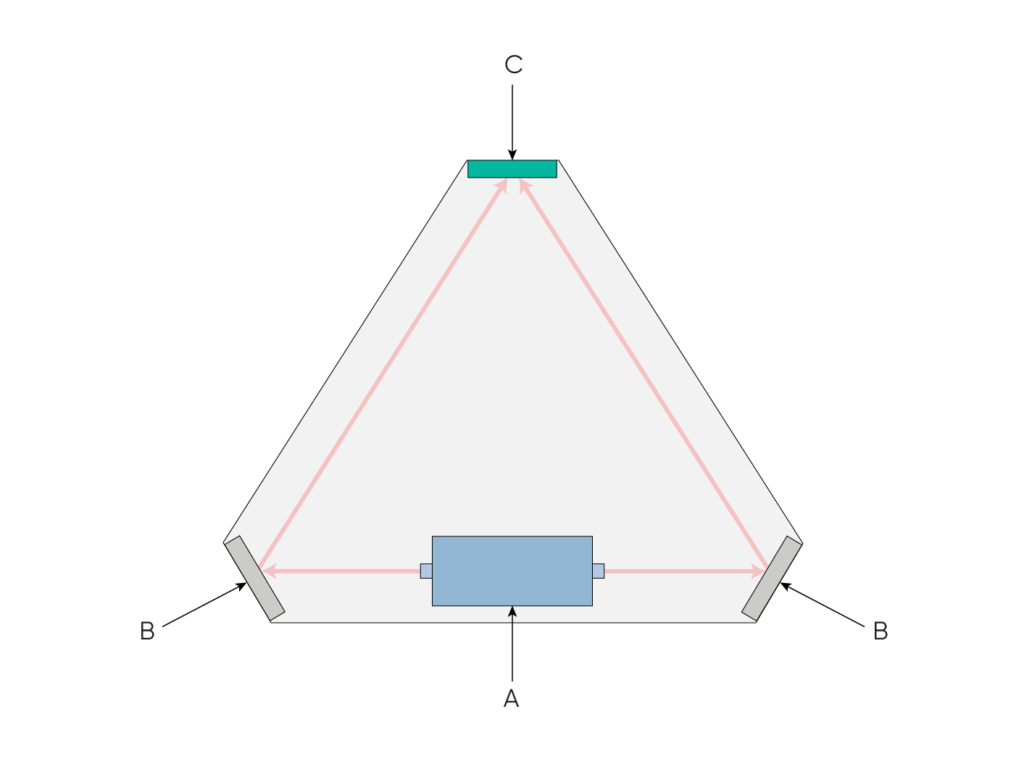
The basic operation of a ring laser gyroscope. A laser source (A) emits beams of light simultaneously in opposite directions. The light bounces off mirrors (B) that direct it to an optical receiver (C).Any rotation of the device will cause the light beams to reach the optical receiver at different times due to the Sagnac effect, which can be extrapolated into a measurement of rotation.
Single-Axis and Hybrid Optical-MEMS Gyroscopes
Some fiber-optic and ring laser gyroscopes are specifically designed for single-axis rotation measurement, frequently enough tailored for applications requiring precise heading (Z-axis) determination, such as in maritime vessels and submarines.
Conversely, hybrid gyroscopic systems merge optical gyroscopes with micro-electromechanical systems (MEMS) gyros. this strategy balances cost,size,and weight by employing high-precision optical gyros for heading while utilizing smaller,more affordable MEMS gyros for roll (X-axis) and pitch (Y-axis).
Read the original article >>


