
Maxtena specializes in the creation of antennas and IoT solutions tailored for autonomous systems,defense,logistics,and various other sectors,positioning itself as a leader in wireless communication technology.
Their latest innovation, the tactical-grade M10HCT-A-TNC GNSS antenna, incorporates Maxtena’s advanced Helicore
® technology, adding to a robust portfolio of reliable wireless connectivity options.
Grasping the essential parameters of antennas is vital for the effective design, selection, and enhancement of antennas across different applications.
This technology can be overwhelming for newcomers, and even seasoned professionals may benefit from a refresher.
To address this need, Maxtena has published a extensive glossary of terms frequently encountered in the realms of radio frequency (RF) and antenna technology, available below.
Glossary of RF and Antenna Terms
Frequency
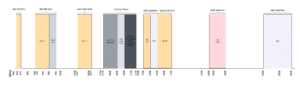
The frequency of an antenna indicates the spectrum of radio frequencies it can send or receive. Antennas are engineered to function within a designated frequency range,and their effectiveness can fluctuate based on the frequency of the signals they handle. the specific frequency range is dictated by the antenna’s design and construction.
Efficiency
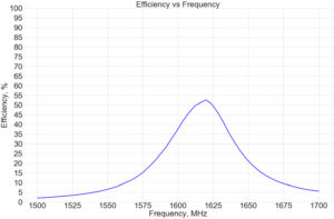
Antenna efficiency measures how well an antenna transforms input power into radiated power, typically expressed as a percentage. This is calculated by dividing the radiated power by the input power and multiplying by 100.
An antenna with high efficiency will radiate most of the input power, while a less efficient one will lose power due to resistance or other factors. Efficiency is a critical consideration in antenna design and selection, as it influences the performance and range of communication systems.
Polarization
Polarization describes the orientation of the electric field of electromagnetic waves transmitted or received by an antenna. Antennas are typically designed for specific polarizations, which can be vertical, horizontal, or circular. The polarization is steadfast by the orientation of the antenna elements relative to the ground. For instance, a vertical antenna has elements positioned perpendicular to the ground, while a horizontal antenna has elements parallel to it.
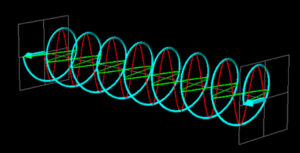
Right-Hand Circular Polarization
Right-hand circular polarization (RHCP) refers to a polarization type where the electric field of the radio wave rotates clockwise as it travels. This contrasts with left-hand circular polarization (LHCP), where the electric field rotates counterclockwise.
Circular polarization is frequently utilized in satellite communications, as it enhances performance in environments with substantial atmospheric noise or interference. antennas designed for RHCP signals have elements arranged in a circular configuration, oriented to achieve the desired polarization.
Antenna Gain
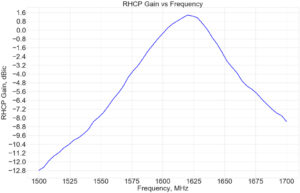
Antenna gain quantifies the enhancement in signal strength as it passes through an antenna,typically measured in decibels (dB). High-gain antennas amplify input signals and radiate them over a broader area, while low-gain antennas produce weaker signals. Gain is a crucial metric for comparing antenna performance and should be considered when selecting an antenna for specific applications.
Axial Ratio
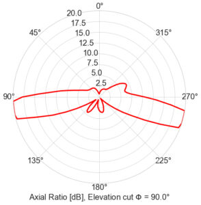
The axial ratio of an antenna measures the ellipticity of its radiation pattern, defined as the ratio of the major axis to the minor axis in a given plane. Typically expressed in decibels (dB), the axial ratio is crucial for assessing the performance of circularly polarized antennas.
An ideal circularly polarized antenna has an axial ratio of 0 dB, while an axial ratio above 0 dB indicates an elliptical radiation pattern. Factors such as design, construction, and operating habitat can influence an antenna’s axial ratio.
Return Loss
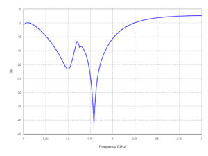
Return loss quantifies the power reflected back towards the source due to standing waves on the transmission line, resulting from mismatched antennas or lines. It measures how effectively an antenna transmits or receives signals, typically expressed in decibels (dB). A well-functioning antenna generally has a return loss of less than -10 dB across its operational frequency range,indicating efficient signal transmission and reception.
VSWR

The voltage standing wave ratio (VSWR) measures the standing wave ratio on the transmission line of an RF system. It is indeed defined as the ratio of the maximum voltage to the minimum voltage along the line. A VSWR of 1:1 indicates a perfect match, while a ratio greater than 1:1 signifies a mismatch between the system and the load.
Radiation Pattern
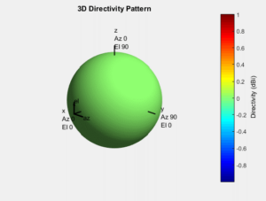
The radiation pattern of an antenna illustrates the directional dependence of radio wave strength.
Types of radiation patterns include:
1. Isotropic
2. Omnidirectional
3. Pencil-beam
4. Hemispherical
Beamwidth
Beamwidth refers to the angular width of an antenna’s radiation pattern, typically measured in degrees.It is indeed defined as the angle between points on the radiation pattern where the power is at least half of the peak power. The design and construction of the antenna influence its beamwidth, which can be affected by the size and shape of its elements and the operating frequency. Antennas with narrow beamwidths concentrate their radiation into smaller areas, while those with wider beamwidths produce more diffuse patterns.
Bandwidth
Bandwidth indicates the range of frequencies over which an antenna can operate effectively, typically measured in hertz (Hz) or as a percentage of the center frequency. The design and construction of the antenna determine its bandwidth. Antennas with wider bandwidths can function across a broader frequency range. Bandwidth is a critical factor in antenna selection,as it impacts performance and range.For instance, a wideband antenna can transmit and receive a larger variety of signals but may also be more prone to interference.
Phase Center Offset
The phase center offset of an antenna is the difference between its phase center and its physical center. The phase center is where the phase of the radiated electromagnetic field is uniform in all directions, while the physical center is the geometric center of the antenna’s elements. Factors such as design and construction can affect the phase center offset, which may vary with frequency.
Phase Center Variation
Phase center variation (PCV) measures the difference in the phase center of an antenna across different frequencies and angles. typically expressed in units of length, PCV indicates the stability of the phase center over a range of frequencies. Antennas with low PCV exhibit stable phase centers, while those with high PCV may show variations at different frequencies. PCV is crucial in antenna design and operation, as it can influence performance and accuracy.
LNA Gain
A low-noise amplifier (LNA) amplifies weak signals with minimal noise. The gain of an LNA measures the increase in signal strength,typically expressed in decibels (dB),calculated by comparing the input signal power to the amplified output signal power. An LNA with high gain produces a stronger output signal, making gain an important consideration when selecting an LNA for specific applications.
Noise figure
The noise figure of a device measures the noise added to the signal it processes,typically expressed in decibels (dB). it is calculated by comparing the noise power at the output to the noise power at the input. Devices with low noise figures add minimal noise, while those with high noise figures contribute more noise. The noise figure is a vital factor in selecting equipment for communication systems, as it affects performance and sensitivity.
Out-of-band Rejection
Out-of-band rejection quantifies a device’s ability to filter out signals outside its operational frequency range, typically expressed in decibels (dB). It is calculated by comparing the power of signals within the operational range to those outside it. Devices with high out-of-band rejection effectively eliminate unwanted signals.
Group Delay
Group delay measures the time taken for a signal to traverse a system or device, reflecting the difference between the input and output signal phases at a specific frequency. It describes the response of RF electronic systems to input signals and can evaluate their ability to accurately reproduce and process signals. Depending on system design, group delay may remain constant or vary with frequency. A flat group delay response across the operational frequency range is often desirable,enhancing the clarity and performance of the processed signal.
Group Delay Variation
Group delay variation refers to changes in group delay over a specific frequency range. This variation is significant in applications where it can impact the performance of systems like filters and modulators. Generally,systems with low group delay variation are preferred,as they allow signals to pass through with minimal distortion.
Conclusion
A solid understanding of key antenna parameters is essential for the design, selection, and optimization of antennas across various applications. Each parameter offers insights into an antenna’s performance characteristics, enabling engineers to make informed decisions tailored to specific needs.
By considering these parameters collectively, engineers can create antennas that fulfill the unique requirements of their applications, whether in wireless communication, radar systems, satellite communication, broadcasting, or other wireless technologies.Furthermore, optimizing these parameters ensures efficient resource utilization and enhances overall system performance.


