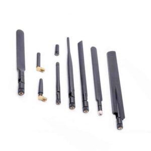
Doodle Labs has published a comprehensive guide aimed at helping customers navigate the critical choices involved in selecting an antenna for their communication systems,covering aspects such as frequency and bandwidth,polarization,gain and directivity,and form factor.
In the development of your communication system, selecting the right radio is paramount, but the choice of antennas is nearly as crucial.
Even if you have the finest radios available (which we confidently assert we do),using antennas that are not tailored to your specific request can led to system failures or substantially diminished performance.
Regrettably, there is no straightforward answer to the question, “What is the ideal antenna for the Smart Radio?” The response is contingent upon your specific objectives.
This guide serves to inform you about the key considerations you will likely face when selecting an antenna. For basic indoor testing, we suggest utilizing our Evaluation Kits for ease of use.
If you seek tailored recommendations for antennas suited to your project, please reach out to us with details about your application. We are committed to guiding you effectively.
The following sections detail the essential factors to consider when choosing an antenna:
- Frequency and Bandwidth
- Polarization
- Gain and Directivity
- form Factor
Frequency and Bandwidth
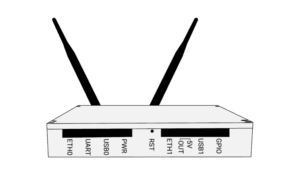
Typically, our clients are already aware of the frequency band they will utilize, as this decision is often made before selecting the Smart Radio. Factors such as application type, geographical location, and end-user requirements influence the choice of frequencies.Below is a table showcasing some Smart Radios along with their respective frequency ranges, while the
Models Index
provides a comprehensive list.
| Model No. | Frequency Range (MHz) | Description | View Specs |
| RM-915-2X |
902-928 MHz |
License-Free ISM Band – USA, Canada, Mexico, Central, South and Latin Americas, australia, New zealand, and China | View Datasheet |
| RM-2450-2X |
2400-2482 MHz |
License-Free ISM Wi-Fi Band (Worldwide) | View Datasheet |
| RM-5800-2X |
5725-5875 MHz | License-Free ISM Band – USA, Canada, mexico, Central, South and Latin Americas, Australia, and New zealand | View Datasheet |
| ACM-DB-3 |
2.4 & 5.8 GHz |
License-Free ISM Bands |
view Datasheet |
| NM-DB-3 |
2.4 & 5.8 GHz | license-Free ISM Bands | View Datasheet |
| ACM-DB-2 |
2.4 & 5.8 GHz | License-Free ISM Bands | View Datasheet |
| NM-DB-2 |
2.4 & 5.8 GHz | License-Free ISM Bands | View Datasheet |
Certain antennas can operate across multiple frequency bands; they may exhibit a broad overall bandwidth while having narrower center bands.For instance, an antenna might cover a range from 698 MHz to 3 GHz, with six specific bands designed for operation within that spectrum.
However,the tradeoff is that performance may not be optimal for any single frequency,but it allows for a range of usable frequencies within one unit. We recommend that, particularly for your final design, you select an antenna that is specifically tuned to the frequencies you will be using.
It’s also important to note that the operating frequency greatly influences the antenna’s size, especially for customers with constraints on size and weight. Higher frequencies correspond to shorter wavelengths,resulting in smaller antennas compared to those designed for lower frequencies.
Polarization
The Smart radio operates as a MIMO radio system, capable of utilizing various antenna polarization schemes to enhance diversity, a key method for ensuring reliable connectivity in challenging environments.
Every antenna has a specific polarization direction, which refers to the oscillation direction of the emitted radiation.
Linear and Circular polarization
Linear polarization occurs in a straight line and can be vertical, horizontal, or at any angle, depending on the antenna’s orientation. The electrical wave of the antenna’s signal oscillates along this straight line.
Conversely, circularly polarized radiation rotates as it exits the antenna (similar to a corkscrew) rather than moving along a single plane. Circular polarization can rotate either clockwise or counterclockwise. Antennas with circular polarization are frequently enough more effective in adverse weather conditions, as they can penetrate rain and other atmospheric disturbances more effectively than linear polarized antennas. Circularly polarized antennas are also advantageous in rapidly changing scenarios, such as with drones, where the antenna orientation is frequently altered.
Choosing the correct antenna polarization is crucial,as both transmitting and receiving antennas must share the same polarization type.Using a vertically polarized antenna with a circularly polarized one will result in a loss of gain, diminishing communication range and affecting the quality of video or data transmission.
Cross Polarization for Diversity
Separating each data stream in a MIMO radio enhances diversity and improves transmission quality. This can be achieved by employing opposite polarizations within each antenna set on the radio.
As a notable example, a Smart Radio can be configured with two linearly polarized antennas positioned at 90 degrees to each other. On the receiving end, the antennas can be aligned similarly to ensure effective signal reception. Cross polarization enhances reliability, particularly when antenna orientation is dynamic, as seen in drones and ground robots.
Gain and Directivity
Antenna gain can be viewed as a “boost” for the signal transmitted from the radio. Higher gain results in improved signal quality, increased data throughput, and extended range. Thus, it is indeed advisable to aim for the highest gain possible that meets the directional coverage requirements and complies with local EIRP regulations.
Gain is typically expressed in dBi. For instance, a gain of 10 dBi indicates ten times the energy compared to an isotropic antenna, which radiates power uniformly in all directions.
in passive antennas, gain is achieved by directing the antenna’s radiation in a specific direction rather than dispersing it evenly like an isotropic antenna. This approach enhances the strength of the “boost” but limits radiation in other directions. Generally, higher gain antennas are larger in size.
Customers in mobile robotics and UAV sectors should consider the altitude at which their vehicles will operate and seek antennas that maximize horizontal gain while still providing the necessary spatial coverage.
Designers of drone systems often opt for low-gain omnidirectional antennas (e.g., 3 dBi) oriented downwards to minimize weight on the aircraft. Conversely, a higher gain omnidirectional or tracking antenna is typically used on the ground, directed upwards.
Form Factors
We will discuss two primary types of antennas: omnidirectional and directional. the selection of form factor is largely influenced by the directivity considerations mentioned earlier.
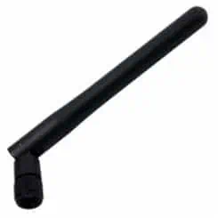
Omnidirectional Antennas
Omnidirectional antennas are engineered to radiate uniformly in all directions on a single plane. This type of antenna is versatile and well-suited for various applications where nodes are mobile and movement is unpredictable. The common black rubber duck antenna found on many home routers is an example of an omnidirectional antenna.
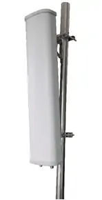
Directional Antennas
As the name suggests, a directional antenna is designed to concentrate its radiation in a specific direction. this design enhances gain and reduces interference from other directions. Sector antennas, for instance, can focus their coverage up to 180°.
long-range antennas are a subset of directional antennas,specifically designed for long-distance point-to-point connections. their coverage angles typically range from 12° to 25°, necessitating precise alignment with the opposing antenna. For extensive links required for UAVs, a dish antenna may be employed with tracking technology to ensure it remains aimed at the aircraft.


