
This whitepaper from Maxtena explores the comparative performance of patch and helix antennas, analyzing their respective advantages and disadvantages to assess their effectiveness in the context of multipath propagation.
1. Overview of Patch Antennas
Patch antennas are among the most prevalent types of GNSS antennas, utilized across a wide range of civilian and military wireless applications.These antennas feature a flat conductive surface mounted on a dielectric substrate, with a ground plane situated beneath.
They are especially suitable for scenarios were compactness and cost-effectiveness are essential.Patch antennas can be seamlessly integrated into portable navigation devices, including smartphones and PDAs. Ceramic patch antennas are especially favored due to their diverse size options, ranging from 40 x 40 mm to as small as 10 x 10 mm, with 25 x 25 mm being the most common size.
Nonetheless, the performance of patch antennas is influenced by the size of the ground plane. According to fundamental principles of physics, a smaller antenna captures less signal energy from the sky, leading to reduced overall gain. Conversely, when a patch antenna is mounted on a larger ground plane (e.g., 70 x 70 mm), it can achieve a high gain of approximately 10 dBi.
2. Understanding Helix Antennas
The quadrifilar helicoidal antenna (QFH) is extensively employed in various fields, including UAVs, unmanned ground vehicles (UGVs), unmanned systems, high-precision navigation, military applications, smart agriculture, and handheld GNSS devices.
This antenna comprises a helical design with four evenly spaced wire elements, energized by currents that are 90° out of phase, resulting in circular polarization with a minimal axial ratio. Helix antennas are particularly favorable in applications where multiple orientations are possible due to their broad elevation angle coverage.
They are lightweight,durable,and exhibit excellent navigational capabilities,along with strong resistance to multipath propagation. Additionally, helix antennas are compact and do not necessitate a ground plane, making them highly adaptable and easy to install in various settings.
3. Pros and Cons of patch and Helix Antennas
Benefits
Patch:
- Compact and low-profile design
- Simple integration into devices
- High gain and directivity for low-elevation angles
- Single excitation requirement
- Versatile and adaptable
- Can be engineered for linear or circular polarization
- Cost-effective
Helix:
- Lightweight construction
- Sturdy and long-lasting
- Extensive elevation angle coverage
- Can be configured for omnidirectional or directional radiation patterns
- highly versatile and adaptable
- Exhibits circular polarization with a low axial ratio, enhancing resistance to multipath effects
- No ground plane required
- Broad bandwidth capabilities
- Ability to track nearly all visible satellites, resulting in excellent dilution of precision (DOP)
Drawbacks
Patch:
- Dependent on ground plane size
- Narrow bandwidth limitations
- Susceptible to variations in dielectric properties, manufacturing tolerances, and nearby structures
- Limited power handling capacity
- Relatively narrow beamwidth
Helix:
- Complex design and feeding requirements (additional components needed for proper element excitation)
- Lower gain and directivity compared to patch antennas
- Cylindrical shape and larger size may limit some applications
- Generally more expensive than patch antennas
4. Axial Ratio and Its Role in Multipath Rejection
In assessing antenna performance, the axial ratio (AR) is a critical metric. It serves as an indicator of the purity of circular polarization. To fully grasp this concept, it is essential to first understand what polarization entails.
Understanding Antenna Polarization
Antenna polarization describes the orientation of the electric field of electromagnetic (EM) waves transmitted or received by an antenna. Polarization can be linear (where the electric field follows a straight line), circular (where the electric field traces a circular path), or elliptical (a more general form that is neither linear nor circular).
Antennas are typically designed to transmit and receive radio waves with a specific polarization.For optimal electromagnetic power transfer, it is crucial that both the transmitting and receiving antennas share the same polarization.
Most satellite systems utilize circular polarization, which can be classified as either right-hand circular polarization (RHCP) or left-hand circular polarization (LHCP). RHCP follows the motion of the fingers of the right hand when the thumb points outward (clockwise), while LHCP rotates counter-clockwise.
Defining Axial Ratio
The axial ratio quantifies the relationship between the major and minor axes of the circular polarization pattern. A smaller difference between these axes indicates a pattern that closely resembles a perfect circle. Consequently, an ideal circularly polarized antenna achieves an axial ratio of 1 (0 dB). In satellite communications, a low axial ratio is vital for several reasons, particularly in mitigating multipath propagation.
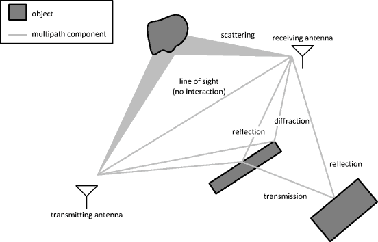
Understanding Multipath Propagation
Multipath propagation can be likened to a complex interplay of electromagnetic waves taking various routes to their destination. As wireless signals traverse space, they encounter obstacles that reflect the signals in multiple directions, akin to a game of cosmic ping-pong where signals bounce off buildings, trees, and other surfaces.
Though, this phenomenon can lead to complications. the diverse signal paths, each with different delays, amplitudes, and phases, can create interference when they reach the receiver. This interference can result in signal fading, distortion, and data errors.
Thus, the polarization purity of an antenna, as indicated by the axial ratio, is crucial for minimizing the effects of multipath propagation in satellite interaction systems.Circularly polarized electromagnetic waves tend to alter their polarization upon reflection from conductive surfaces. As an example, a right-hand circularly polarized wave reflects as left-hand circularly polarized, and vice versa, similar to how a mirror inverts an image.
Antennas with a very low axial ratio are more effective at rejecting reflected, destructive signals compared to those with a high axial ratio. Such as, an ideal right-hand circularly polarized antenna with an axial ratio of 0 dB can fully reject all reflected left-hand circularly polarized waves, ensuring optimal signal quality and preventing data loss.
Quadrifilar helical antennas excel in this regard, showcasing some of the lowest axial ratios among commercially available antennas across a wide frequency range and various applications. Their cylindrical design aligns naturally with the circular electric field pattern required for optimal circular polarization.
In contrast,patch antennas with a sufficiently large ground plane can achieve higher gain values,which enhances their ability to reject signals originating from the horizon,where many reflected signals typically arise.
However, in scenarios where reflections come from angles closer to the zenith—such as in urban environments with numerous tall structures—multipath propagation can have a more significant impact.
Ultimately, in applications where minimizing multipath propagation is critical, helix antennas are the preferred choice, while patch antennas are more suitable in situations where higher gain and a low-profile design are prioritized.


