This article by Tyto Robotics delves into methods for adjusting electric motor speed, focusing on the relationship between Pulse-Width Modulation (PWM) duty cycle, Electronic Speed Controller (ESC) output voltage, and the calculation of motor KV to RPM.
Electric motors play a crucial role in various tools and vehicles, notably in drones and electric aircraft, where they are typically managed through a throttle controller and an ESC.
When you increase the throttle on your controller, you are essentially boosting the electrical power drawn from your battery and supplied to the motor via the ESC. To decelerate the motor, simply reduce the power; conversely, to accelerate, increase the power.
But what underlies the process of controlling motor speed?
Adjusting Electric Motor Speed: A Guide
regulating the speed of an electric motor boils down to managing the electrical power supplied to it. In this discussion, we will focus on a steady-state scenario where acceleration is not a factor.
Specifically, for a given mechanical load, increasing the voltage results in a higher speed. Alternatively, reducing the load on the motor can also achieve this effect.
Examining the equation for angular velocity:
where:
ω = angular velocity
V = voltage
T = torque
Kᴛ = motor torque coefficient
R = resistance / load
Kᴇ = back EMF constant of the motor
This equation illustrates that angular velocity (or motor speed, measured in RPM) is directly proportional to voltage and inversely proportional to torque.
Thus, to enhance motor speed, one can either a) increase the voltage supplied or b) decrease the torque. Since altering torque often necessitates redesigning the system,increasing voltage is typically the more straightforward approach.
It’s also important to note that there are minor losses within the ESC, meaning the input voltage is usually slightly higher than the output voltage to the motor, typically by a few percentage points.
Understanding Motor Speed via PWM Duty Cycle and ESC Voltage
Motor speed adjustments can also be described through the ESC protocols that manage power delivery.
As an exmaple, with PWM, the signal sent from the controller (measured in microseconds) corresponds to a percentage of the maximum voltage that can be delivered to the motor and ESC.
The PWM signal ranges from 1000 µs (no throttle) to 2000 µs (full throttle),with intermediate values representing a duty cycle between 0% and 100%.
At 0%, no power is supplied to the ESC and motor, while at 100%, power is continuously delivered.
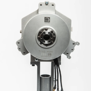
Xoar TA130 motor mounted on test stand
Variations exist among ESC manufacturers, but the correlation between duty cycle and motor speed generally aligns with the average output voltage of the ESC.
The ESC generates an approximate sine wave output for each phase. At 50% output, the sine wave’s amplitude is about half that of a 100% output. However, most ESC electronics operate in an on-off state, resulting in a less smooth signal than a perfect sine wave.
Differences among motor and ESC manufacturers can introduce non-linearities,so it’s advisable to characterize the motor and ESC using a dynamometer for practical applications.
digital protocols like Dshot and Oneshot utilize the same duty cycle principle but offer faster signal transmission and varied delivery patterns.
You may also encounter duty cycle values ranging from 0 to 1024, stemming from the advancement of 8-bit controllers. This means 2 options (on/off) with an 8-bit system yield 2¹⁰ → 1024.
This system can also help determine the ESC’s output voltage.
For instance, a value of 796 indicates 78% ‘on’ relative to a 100% output.
Calculating Motor KV to RPM
In a no-load scenario, the motor’s KV rating can be used to estimate its speed based on the supplied voltage.
As outlined in our previous article on calculating motor KV, we can substitute Back EMF with input voltage in this equation to estimate the rotational speed of the electric motor.
For example, consider the
MAD Components’ M50C35 EEE 9 KV motor
. With a maximum voltage of 400 V and a KV rating of 9 KV, we can calculate the maximum speed as follows:
At full throttle, this motor will achieve a speed of 3600 RPM. If we apply only 75% throttle, corresponding to 300 V, the speed would drop to 2700 RPM.
Final Thoughts
This article has highlighted several methods for increasing motor speed.
The most practical approach is to boost the voltage supplied to the motor by increasing the throttle. While reducing torque is another option, it often disrupts the design or intended function of the UAV.


